Improving the Trigger on the Daisy / Avanti Model 499© 2006 by Calvin Smith |
|


|
|
|
|
DisclaimerThe advice in this document is given freely, but when you start working on your guns, you are on your own. YOU are the person making the modifications. YOU are the one that is liable for any accident resulting from any unsafe condition caused by such modifications. YOU agree to this now, or discontinue use of this material now.IntroductionAt the 2006 International BB Gun Championship Match in Bowling Green, Kentucky, I was trying to explain to one fellow how the trigger pull on the gun can be improved and soon, quite an audience had gathered. I thought others might benefit from the work I have done in this area, hence this document now exists. I share it with you, giving back just a bit to the sport I enjoy.The trigger on the Daisy Model 499B, now the Avanti Model 499, leaves a bit to be desired. However, the rulebooks prohibit using anything other than factory-original parts. It is the intent of this writing to describe the modifications I make to the trigger to improve the shooters accuracy potential while maintaining the original configuration and function, without getting sideways of the competitive rulebook. The trigger improvement primarily involves altering the plastic parts. It converts a long, grinding pull into a distance of slack travel followed by a crisp break. If you attempt to make the trigger too light or into too much of a hair trigger, you will disable the safety mechanism and wind up with a gun that will go off if you look at it crossways. That would create a real hazard for your shooter, yourself and anyone else on the line with you, and probably wear out your welcome. Until you have performed this procedure a number of times, I recommend having spare trigger parts on hand, especially the plastic pieces and the springs. |
|
Tools Needed
Removing the Trigger Assembly
|
|
|
|
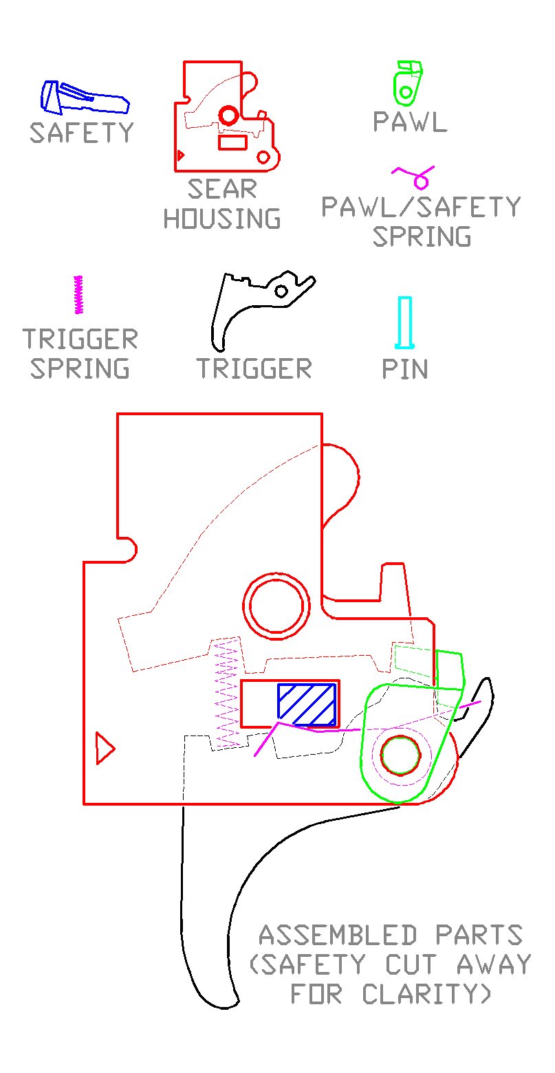
Trigger Disassembly and CleaningThere is a metal pin at the front of the trigger group. Remove it. The trigger group will come apart into 6 distinct parts:
Clean all parts to be free of grease and crud. Check the Pin HoleThe sear housing is a folded metal stamping. The hole that the pin passes through should align correctly from side to side. I have seen them where they had several degrees of misalignment, and theres just nothing much you can do with it when they are messed up like that other than to get another housing assembly. | |
|
|
|
Bevel the PinUsing a flat file, put a small bevel on the point of the pin, making reassembly much easier. |
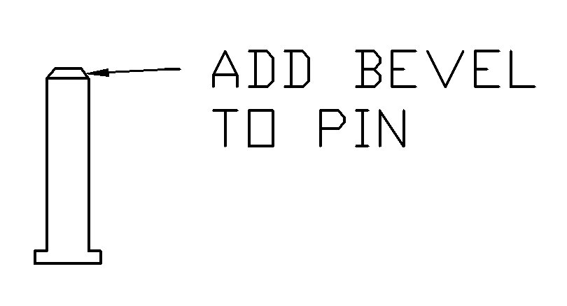 Figure 2
|
Smooth/Deburr the PartsThe sides of the plastic trigger should be smoothed with an emery board, such that the trigger pivots with less drag.With a flat file, dress up the inside edges of the sear housing where the trigger contacts it, to reduce drag on the trigger. Polish the sear plate at the surface where it contacts the pawl, (see figure 3, point "B".) Use an emery board for this, backed up by a popsicle stick to make the emery board stiffer. DO NOT CHANGE THE ANGLE OF THE SEAR/PAWL MATING SURFACE. Just smooth it up. |
|
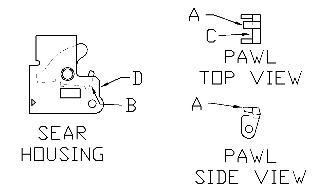 Figure 3
|
|
|
|
|
Preliminary Shortening of the PawlThe object of this step is to shorten the sear-engaging protrusion on the pawl so that the pawl rests on the sear housing when the sear housing and pawl are assembled with the pin, in the cocked position. That is, when point "A" on the pawl engages the notch at point "B" on the sear plate. See figure 3.Using an emery board backed up by a popsicle stick or a small flat file, remove material from the pawl, shortening the sear-engaging surface (point "A") until the crosspiece of the pawl (point "C") has zero clearance with the front edge of the sear housing at point "D". You must be careful to maintain the existing angle of the pawl as you remove material from it. You must check this by assembling the pawl to the sear plate with the pin several times as you remove material from the pawl. See figure 4. You will know you have it right when the sear plate will barely jiggle when the pawl is pressed toward it with the pieces in the cocked position as shown in figure 4. |
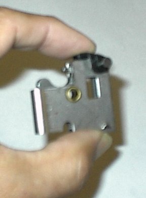 Figure 4
|
|
|
|
Changing the Trigger-to-Pawl EngagementThe object of this step is to modify the trigger-to-pawl engagement so that the pawl does not move when the safety is in the SAFE position and the trigger is pulled. This adjustment is critical to maintaining the function of the safety when we shorten the pawl again in a later step.On the trigger piece, the bump that contacts the pawl (point "A", figure 5) is where we make this adjustment. First, some explanation of the trigger/safety relationship is needed. When the safety is to the rear of the safety slot (point "E",) the bump on the trigger piece (point "B") contacts the safety, preventing the trigger from being fully pulled, but still allowing the trigger to move somewhat. When the safety is forward in the slot, the notch in the trigger piece (point "C") allows clearance for the trigger to be pulled. The movement of the trigger when the safety is to the rear of the slot can cause an accidental discharge if this step is not done correctly. First, assemble the trigger and pawl to the sear housing with the pin and insert the safety in its slot. Hold the assembly between the thumb and index finger, as shown in figure 6, with the pieces in the cocked position and the safety to the rearward position. With the index finger of the other hand, press rearward on the trigger. You will feel the pawl move forward. It is that movement that must be eliminated. Change the angle "A" of the bump on the trigger piece (see figure 7) just until the movement described above is eliminated. It requires several cycles of filing, assembly and testing, disassembly and more filing, etc. IF YOU TAKE OFF TOO MUCH, THE GUN WILL NOT FIRE AT ALL WHEN ASSEMBLED. That puts you in the position of having to try to disassemble a cocked and possibly loaded gun. |
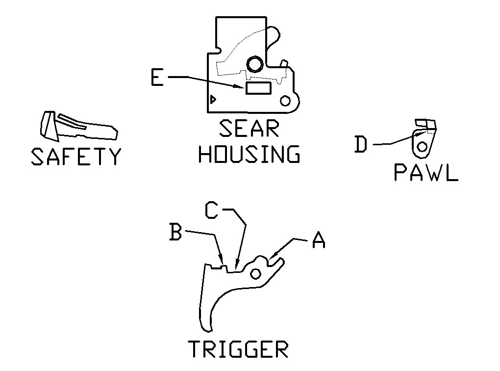 Figure 5
|
|
|
|
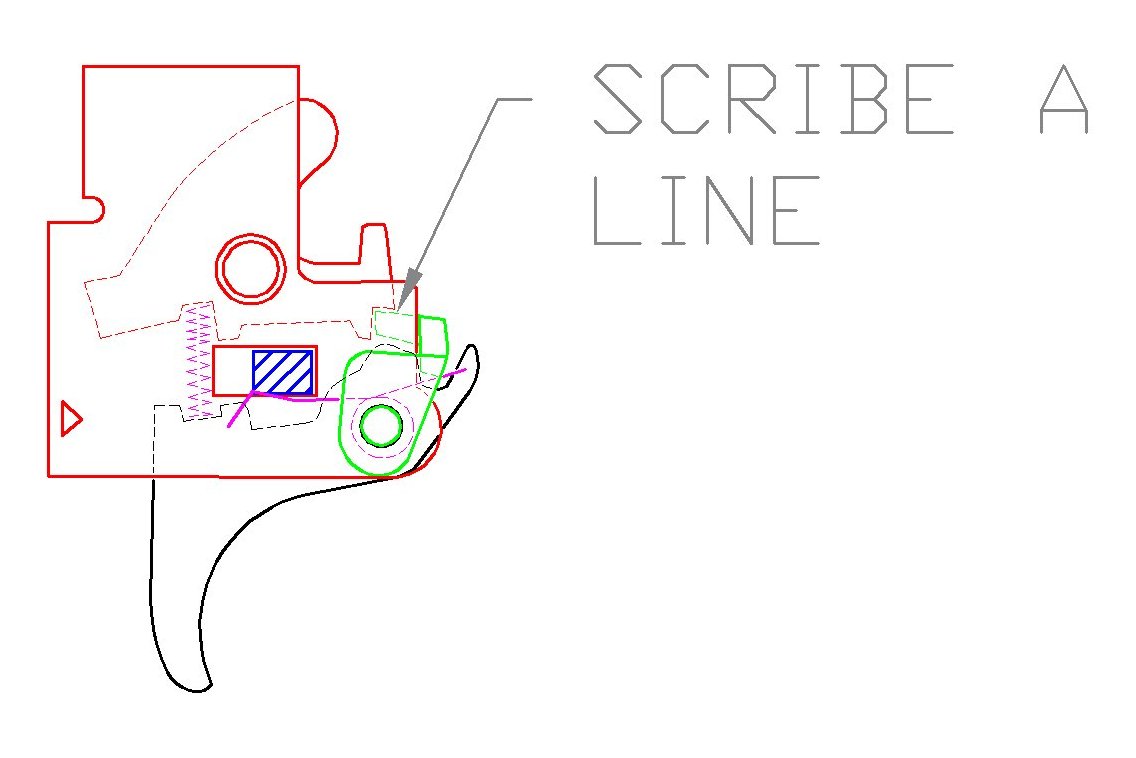
Final Shortening of the PawlThe previous step added slack to the trigger pull. The object of this step is to further shorten the sear-engaging protrusion on the pawl to create a crisp break at the end of that slack travel.With the pieces assembled in the cocked position, use an Exacto knife to scribe a line in the top of the pawl, right at the edge of the sear engagement notch. See figure 8. Disassemble the parts by pulling the pin again. Look at the line you just scribed on the pawl. You can shorten the sear engaging surface of the pawl to within 1/32nd of an inch of that line. IF YOU MAKE IT TOO SHORT, YOU ARE GOING TO HAVE A DANGEROUS, HAIR TRIGGER, A GUN THAT MAY GO OF BY ITSELF OR NOT COCK AT ALL. Using an emery board backed up with a posicle stick, shorten the pawl as described. Be careful to maintain the original angle on the pawl as you remove material. |
|
|
|
|
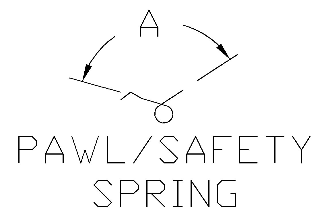 Figure 9
|
A Word or Two About the SpringsThe pawl/safety spring can be opened up a few degrees to lighten the trigger pull. If you open it up too much, the trigger will get dangerously light, and the safety may engage by itself. I increase the angle "A" (see figure 9) by only five degrees, if I do it at all. PUT THE GUN TOGETHER AND TRY IT BEFORE MAKING THIS MODIFICATION. IT MAY BE UNNEEDED. |
|
The trigger spring should not be modified. That spring has a tendency to fall out of the gun, as there is nothing to hold it in, excusing the shallow notches in the sear plate and trigger piece and the compression of the spring. The newer plastic trigger has a little bump molded into the notch that is intended to help retain the spring, but it does not.
My preferred repair for the trigger spring is to carefully drill a 1/16th diameter inch hole, vertically in the triggers spring notch, put in a very small screw (some eyeglass screws work very well in this application,) and cut the head off of the screw with wire cutters. The spring goes over the screw shank when assembled, and I have only seen this repair fail to retain the spring one time, (right before a match.) |
|
Tips on Reassembing the GunMake sure the trigger assembly is in the cocked position when putting it back into the gun. Otherwise, you may have some trouble getting the safety and screws installed.When putting the safety in, make sure the end of the safety spring goes beneath the safety. Do not fully tighten the machine screws that go through the action until the butt stock is in place. After tightening the nuts on the machine screws, give them a good whack or two with a hammer and punch to peen the threads over. That will keep them from coming undone. Pull the trigger before you try to cock the lever. |
|
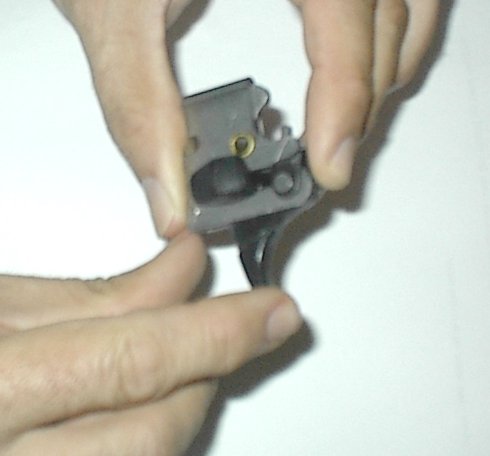 Figure 6
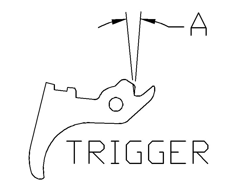 Figure 7
| to get in touch with us: clsmith@txsmith.net |
 © 2006
by Calvin Smith |